SOFiA Modal Radial Filters
SOFiA M/F is a modal radial filter core for spherical microphone arrays. M/F can generate filters for different sphere and microphone configurations and involves soft-limiting of the mode amplification and free field powerloss compensation.

ARGUMENTS
Input
| Name |
Type |
Purpose |
Default |
| N |
int |
Maximum filter order to be generated |
- |
| kr |
float vec or float mtx |
Vector or Matrix of kr values
First Row (M=1) N: kr values Microphone Radius
Second Row (M=2) N: kr values Sphere/Microphone2 Radius
kr_mic; kr_sphere or kr_2 for Rigid/Dual Sphere Configurations.
If only one kr-vector is given using a Rigid/Dual Sphere Configuration: kr_sphere = kr_mic |
- |
| ac |
int |
Array configuration
0: Open Sphere with p Transducers (No PLC!)
1: Open Sphere with pGrad Transducers
2: Rigid Sphere with p Transducers
3: Rigid Sphere with pGrad Transducers (Thanx to Nils Peters!)
4: Dual Open Sphere with p Transducers (Thanx to Nils Peters!) |
- |
| amax_ |
float |
Maximum mode amlification in dB |
- |
| plc |
int |
Free field powerloss compensation
0: Off
1: Full kr-spectrum plc
2: Low kr only -> set fadeover |
- |
| fadweover |
int |
Number of kr values to fade over +/- around min-distance gap of powerloss
compensated filter and normal N0 filters. 0 = auto fadeover |
- |
Output
| Name |
Type |
Purpose |
| dn |
complex float mtx |
Frequency domain radial filter |
| beam |
complex float vec |
Free field kr-Response
Plot it with semilogx(20*log10(abs(beam'))) |
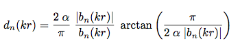
Definitions
The d,,n,, coefficients are defined as:
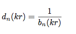
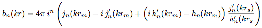
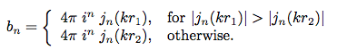
Where b,,n,, depends on the sphere configuration and microphone type:
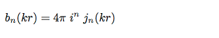
AC0 Open sphere with pressure transducers:
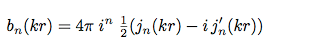
AC1 Open sphere with pressure gradient transducers (cardioids):
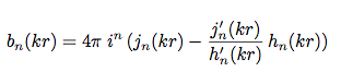
AC2 Rigid sphere with pressure transducers:
Configurations AC3 and AC4 are contributed and implemented by Nils Peters:
AC3 Rigid sphere with pressure gradient transducers (cardioids):
AC4 Dual open sphere with pressure transducers:
j,,n,,(kr) denotes the spherical bessel function of the first kind, h,,n,,(kr)
the spherical hankel function of the second kind and i=sqrt(-1).
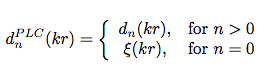
When modal amplification limiting is enabled, d,,n,, is defined as:
Powerloss free-field filters:
BASIC RADIAL FILTERS
The plots show basic radial filters (no limiting, no plc) for N=5 and different array configurations (ac): ac=0 Open Sphere with pressure transducers, ac=1 Open Sphere with pressure gradient transducers (cardioid), ac=2 Rigid Sphere with pressure transducers, ac=3 Open Sphere with gradient transducers (cardioid) and ac=4 Dual Open Sphere with pressure transducers.
SOFT-LIMITING OF THE MODE AMPLIFICATION
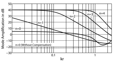
At low kr the modes have to be amplified very hard (see figure above). In real array datasets this required amplification cannot be achieved as the singnal to noise ratio is limited. Strong amplification would raise more noise then useful signal contribution and disturb the array output signal. Therefore the mode amplification has to be limited to reasonable values in real life. This should not be done with hard limits as hard limiting leads to artifacts in the spatial domain. SOFiA M/F therfore uses soft-knee limitation.
The left figures (a) show hard limiting and the right ones (b) soft limiting. Both filtersets are limited to to +40dB
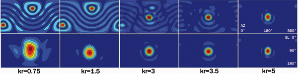
The following figure shows a real measured array response to a plane wave with basic radial filters in the upper row and SOFiA soft-limited radial filters in the bottom row. The response for low kr using basic radial filters is disrupted due to measurement noise. The soft-limited response looses directivity (as expected) but keeps stable.
BEAM RESPONSE
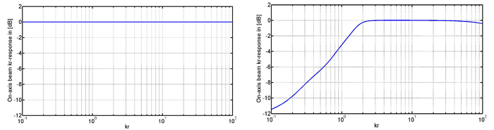
The modal amplification limiting has influence on the kr-response (which can be seen as the array's frequency response). The kr-response can be controlled by plotting the return vector beam e.g. with semilogx(20*log10(abs(beam'))).
FREE FIELD PLC
In a free field the kr-response can be aligned using the N0 mode which offers a good signal to noise ratio. This is called plc (powerloss compensation). The plc leads to a perfect on-axis kr-response. The plc compensation can be applied to the full spectrum or be limited to low frequencies only. In the last case M/F will fade the compensated filter to normal N0 filters at their minimum distance.
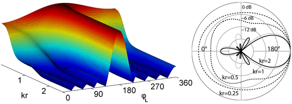
The figure shows the array's azimutal response to a full kr-spectrum plane wave coming from 180°C. The response is compensated on axis but other directions have a raised sensitivity to low frequencies. This leads to an over-emphasized low frequency response in diffuse fields.
FILE(S):
| File |
Type |
OS/Matlab |
| sofia_mf.m |
Help header |
All OS |
| sofia_mf.mexmaci64 |
MEX Core |
OS-X Intel |
| sofia_mf.mexw32 |
MEX Core |
Windows, MATLAB32 |
| sofia_mf.mexw64 |
MEX Core |
Windows, MATLAB64 |
| sofia_mf.cpp |
C/C++ source |
All OS |
| sofia_radial.h |
internal C/C++ header |
All OS |
| sofia_radial.cpp |
internal C/C++ header/source |
All OS |
HEADER
/*
[dn, beam] = SOFIA_MF(N, kr, ac, [a_max], [plc], [fadeover])
------------------------------------------------------------------------------------
|
dn |
Vector of modal 0-N frequency domain filters |
beam |
Expected free field On-Axis kr-response |
------------------------------------------------------------------------------------ |
N |
Maximum transform order |
kr |
ector or Matrix of kr values
First Row (M=1) N: kr values Microphone Radius
Second Row (M=2) N: kr values Sphere/Microphone2 Radius
[kr_mic;kr_sphere for Rigid/Dual Sphere Configurations
! If only one kr-vector is given using a Rigid/Dual Sphere
Configuration: kr_sphere = kr_mic |
ac |
Array Configuration
0 Open Sphere with p Transducers
1 Open Sphere with pGrad Transducers
2 Rigid Sphere with p Transducers
3 Rigid Sphere with pGrad Transducers (Thx to Nils Peters!)
4 Dual Open Sphere with p Transducers (Thx to Nils Peters!) |
a_max |
Maximum modal amplification limit in [dB] |
plc |
OnAxis powerloss-compensation
0 Off
1 Full kr-spectrum plc
2 Low krr only -> set fadeover |
fadeover |
Number of kr values to fade over +/- around min-distance
gap of powerloss compensated filter and normal N0 filters.
0 = auto fadeover |
*/ |
|
The M/F core involves Bessel and Hankel functions provided by the peer-reviewed BOOST C++ Math Library under the BOOST Software License. |

